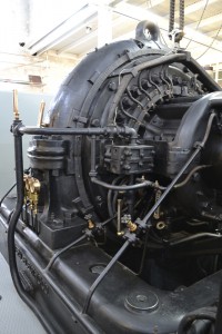
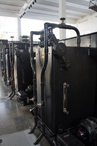
Alternatorn

The alternator

The transmitter set consists in all essentials of three parts, the driving motor, a gear drive and the high frequency generator, commonly called the alternator. They are assembled on a solid base of steel. The weight of the complete transmitter set is about 50 tons.


TElmotorn2he driving motor

The driving motor is an induction motor with the power of 500 HP (about 370 kW). The stator is two- phase, which is extremely rare. The supply voltage is nominally 2200 V. The two-phase supply is obtained from two Scott-coupled transformers in a separate building. When the driving motor rotates with 711.3 rpm, the high frequency generator gives the correct frequency. The rotor winding is three-phase and is connected to variable liquid resistors through slip rings.


VäxellådanThe gear drive

The gear drive increases the speed of the driving motor (711.3 rpm) to the speed of the high frequency generator of 2115 rpm.


 HögfrekvensgeneratorThe high frequency generator

The high frequency generator has a very different design. This is caused by the fact that it is supposed to produce a frequency of 17200 Hz, which is an extremely high frequency for rotating electrical machines. In order to keep the iron losses at a reasonable level, the stator is wound from very thin iron ribbon, unlike traditional alternating current machines, whose stators are constructed from iron sheets that are pressed together.

Also the rotor of the high frequency generator has a very different design. Normally, the rotor of an alternating current machine has a winding fed by DC (direct current) in order to achieve a rotating magnetic field in the stator. The rotor of the high frequency generator is a steel disc, 1.6 m in diameter and 7.5 cm thick at the periphery. The steel disc has no winding. Instead, 488 slots are milled at the periphery. The slots are filled with non-magnetic material (brass), in order to reduce the air friction.

The magnetic flux is generated by a field coil, situated outside the stator. The stator is designed to encircle the periphery of the rotor. The magnetic flux is conducted through the periphery of the rotor via the stator. The air gaps between the rotor disc and the stator are less than 1 mm wide. On the stator there are 64 armature windings that collect the variations of the magnetic flux. The variations arise when magnetic steel and non-magnetic material passes through the magnetic flux. Each armature winding gives 100 V and 30 A, which is conducted to the output transformers.

An interesting detail on the high frequency generator is the device that keeps the rotor disc centred in the middle of the stator, independent of the changes of length of the rotor shaft as a result of varying temperature.

Nominally, the high frequency generator has a power of 200 kW. In normal telegram transmission this power was seldom used and only the amount of power needed for good readability in USA was generated. Nowadays when the machine is run it is not excited very hard. When transmitting, the generator power is about 80 kW.


Vätskemotstånd2

The liquid resistors

Two liquid resistors are used as variable rotor resistances for the Alexanderson unit’s electric motor. A third liquid resistor is available as a spare unit.

The liquid resistors consist of approx. 2 m high containers, in which there are stainless steel electrodes. Water mixed with sodium carbonate (baking soda) flows in the resistors and the liquid level is regulated by motor-driven “dampers” that are controlled from the control panel. This regulates the resistance between the steel electrodes and thus the rotor resistance is controlled. The heat that forms in the liquid is cooled off via a heat exchanger to the station’s cooling water system.

The one liquid resistor is used to regulate the speed of the Alexanderson alternator and thus the frequency of the station when no signal is being transmitted. The second fluid resistor is connected in parallel with the first when the signal is sent and thus reduces the rotor resistance to give the electric motor more torque, so that the speed is maintained constant even when the generator is loaded.


Antenntorn2The multiple antenna

The Multiple antenna is carried by six antenna towers. Each antenna tower is 127 m high and the cross arm is 46 m wide. Between the towers are eight leaders (originally twelve leaders) for the antenna current. Radio waves are radiated from the vertical antenna conductor, one from each tower.

Subscribe!

Be the first to know about upcoming SAQ transmissions by subscribing to our newsletter.

No, thanks!